リニアガイドをArduino+JetsonNano+Webカメラで動作させてみたのでその備忘録用の記事となります。
まずはステッピングモーターを動かしてみる
Arduino と A4988 でステッピングモーターを制御する方法
TB6600を使ってステッピングモータをArduinoで動作させる
上記の記事を参考にしてステッピングモーターを動かしてみます。
先にA4988のほうで動かしてみました。
ようやくステッピングモーターを動かせました。結局かなり時間かけてしまいました。甘くない。 pic.twitter.com/ylB5Ske3wn
— Kazuki (@RoomKazuki) June 15, 2022
TB6600のほうでも動かしてみました。
TB6600のモータードライバーのほうでも動かすことできました。
ここまでが基礎で次は応用編になりそうです。 pic.twitter.com/NqSlLscGp5— Kazuki (@RoomKazuki) June 17, 2022
TB6600のインターフェース
TB6600のインターフェースはこのようになっている。
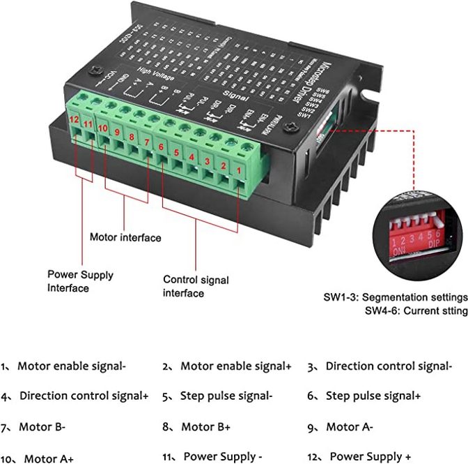
配線はこのように接続している。
PUL+,DIR+,ENA+ ⇔ Arduinoの5Vを接続
DIR- ⇔ ArduinoのPin12を接続、0Vまたは5Vを入れて回転の向きを変更
ENA- ⇔ ArduinoのPin11を接続、5Vでステッピングモーターが動かすことができ、0Vでは動かせない
PUL- ⇔ ArduinoのPin13を接続、パルス信号を入れて回転数と速度を制御
GNDとVCC ⇔ 駆動用の電源(9V~42V)を接続、ステッピングモーターの仕様に合わせる
簡単なコードは以下の通り。
|
1 2 3 4 5 6 7 8 9 10 11 12 13 14 15 16 17 18 19 20 21 22 23 24 25 26 27 28 29 30 31 |
#include <A4988.h> const int MOTOR_STEPS = 400; const int DIR = 12; // DIR- const int STEP = 13; // PUL- int relay_pin = 11; // ENA- float rpm = 120; int microsteps = 30; A4988 stepper(MOTOR_STEPS, DIR, STEP); void setup() { pinMode( DIR, OUTPUT ); pinMode( STEP, OUTPUT ); pinMode( relay_pin, OUTPUT ); stepper.begin(rpm, microsteps); Serial.begin(115200); } void loop() { digitalWrite(relay_pin, HIGH); Serial.println(digitalRead(relay_pin)); stepper.rotate(360); delay(1000); stepper.rotate(-360); delay(1000); digitalWrite(relay_pin, LOW); Serial.println(digitalRead(relay_pin)); } |
設定方法についてはこちらの動画がとても参考になる
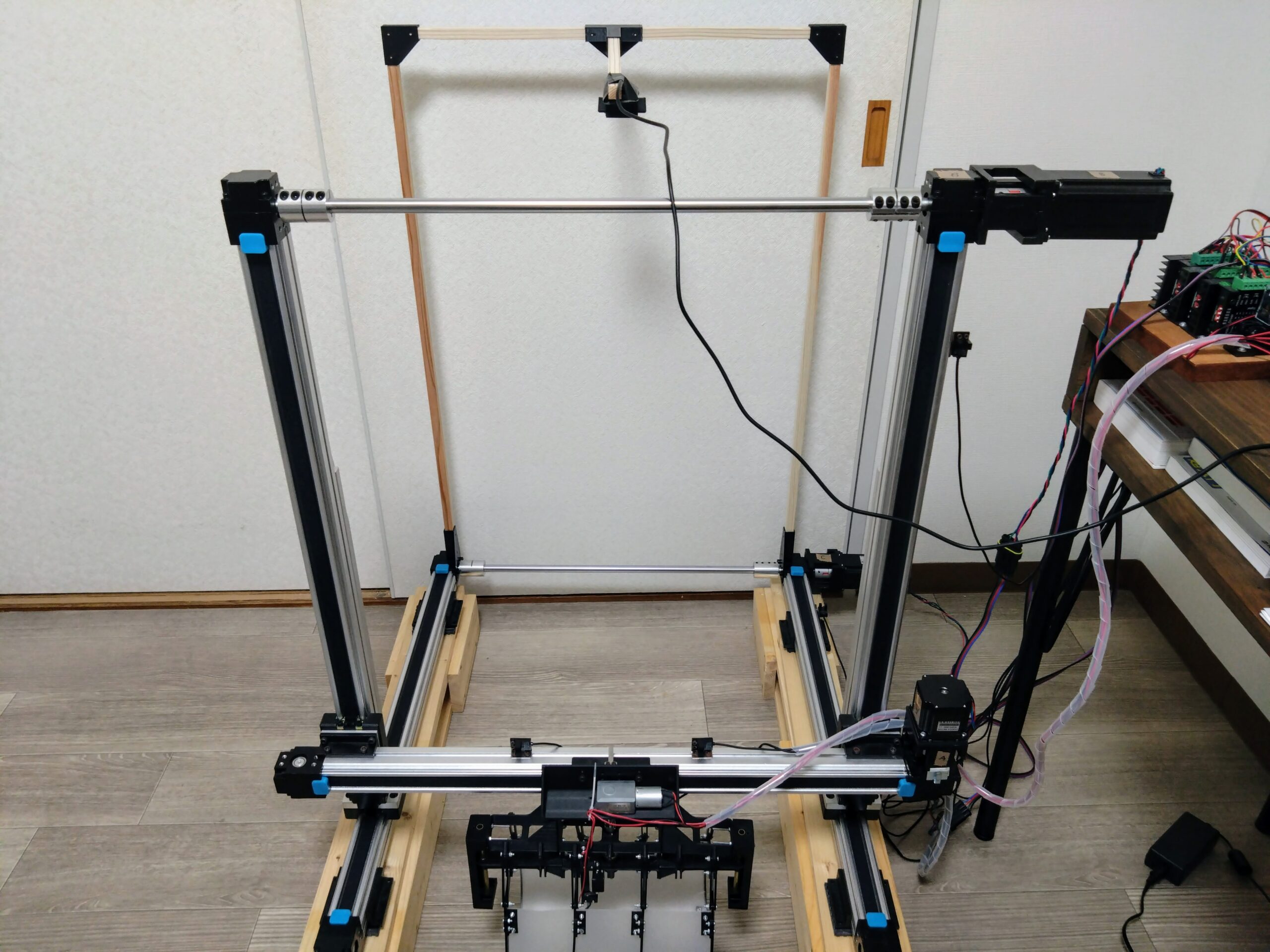
リニアガイドを組み立てて動かしてみた
リニアガイドを組み立てて動かしてみたときのコードは以下の通り。TB6600とArduino MEGAを使用し、X軸・Y軸・Z軸にはそれぞれ2個ずつリミットセンサを取り付けている。
参考にしたのはこちらのページ
How To Control a Stepper Motor with A4988 Driver and Arduino
小型リニアアクチュエータをArduino+A4988+CNCシールドで駆動させる
|
1 2 3 4 5 6 7 8 9 10 11 12 13 14 15 16 17 18 19 20 21 22 23 24 25 26 27 28 29 30 31 32 33 34 35 36 37 38 39 40 41 42 43 44 45 46 47 48 49 50 51 52 53 54 55 56 57 58 59 60 61 62 63 64 65 66 67 68 69 70 71 72 73 74 75 76 77 78 79 80 81 82 83 84 85 86 87 88 89 90 91 92 93 94 95 96 97 98 99 100 101 102 103 104 105 106 107 108 109 110 111 112 113 114 115 116 117 118 119 120 121 122 123 124 125 126 127 128 129 130 131 132 133 134 135 136 137 138 139 140 141 142 143 144 145 146 147 148 149 150 151 152 153 154 155 156 157 158 159 160 161 |
const int MOTOR_STEPS = 400; const int X_PUL = 22; // PUL- const int X_DIR = 23; // DIR- const int X_ENA = 24; // ENA- const int Y_PUL = 25; // PUL- const int Y_DIR = 26; // DIR- const int Y_ENA = 27; // ENA- const int Z_PUL = 28; // PUL- const int Z_DIR = 29; // DIR- const int Z_ENA = 30; // ENA- const int X_LIMIT_SENSOR_1 = 2; const int X_LIMIT_SENSOR_2 = 3; const int Y_LIMIT_SENSOR_1 = 4; const int Y_LIMIT_SENSOR_2 = 5; const int Z_LIMIT_SENSOR_1 = 6; const int Z_LIMIT_SENSOR_2 = 7; //int Speed = 1000; // 500pps(hz) //int Speed = 500; // 1000pps(hz) /400 = 2.5 回/s × 60s = 150 回/min int Speed = 400; // 1250pps(hz) /400 = 3.125 回/s × 60s = 187.5 回/min void setup() { pinMode( Y_DIR, OUTPUT ); pinMode( Y_PUL, OUTPUT ); pinMode( Y_ENA, OUTPUT ); pinMode( Y_LIMIT_SENSOR_1, INPUT ); pinMode( Y_LIMIT_SENSOR_2, INPUT ); pinMode( X_DIR, OUTPUT ); pinMode( X_PUL, OUTPUT ); pinMode( X_ENA, OUTPUT ); pinMode( X_LIMIT_SENSOR_1, INPUT ); pinMode( X_LIMIT_SENSOR_2, INPUT ); pinMode( Z_DIR, OUTPUT ); pinMode( Z_PUL, OUTPUT ); pinMode( Z_ENA, OUTPUT ); pinMode( Z_LIMIT_SENSOR_1, INPUT ); pinMode( Z_LIMIT_SENSOR_2, INPUT ); Serial.begin(115200); Speed = setrpm(150); // 10rpm ~180rpm程度 Serial.println(Speed); } void loop() { digitalWrite(X_ENA, HIGH); digitalWrite(Y_ENA, HIGH); digitalWrite(Z_ENA, HIGH); ////////////////////////////////////////////////////////// digitalWrite(X_DIR, LOW); //Changes the rotations direction // Makes 200 pulses for making one full cycle rotation for (int x = 0; x < 400; x++) { digitalWrite(X_PUL, HIGH); delayMicroseconds(Speed); digitalWrite(X_PUL, LOW); delayMicroseconds(Speed); if (digitalRead(Z_LIMIT_SENSOR_2) == 0) { Serial.println("Z_LIMIT_SENSOR_2 Z ON"); break; } } delay(1000); // One second delay digitalWrite(X_DIR, HIGH); // Enables the motor to move in a particular direction // Makes 400 pulses for making two full cycle rotation for (int x = 0; x < 400; x++) { digitalWrite(X_PUL, HIGH); delayMicroseconds(Speed); digitalWrite(X_PUL, LOW); delayMicroseconds(Speed); if (digitalRead(Z_LIMIT_SENSOR_1) == 0) { Serial.println("Z_LIMIT_SENSOR_1 Z ON"); break; } } delay(1000); ////////////////////////////////////////////////////////// digitalWrite(Y_DIR, HIGH); // Enables the motor to move in a particular direction // Makes 200 pulses for making one full cycle rotation for (int x = 0; x < 400; x++) { digitalWrite(Y_PUL, HIGH); delayMicroseconds(Speed); digitalWrite(Y_PUL, LOW); delayMicroseconds(Speed); if (digitalRead(Y_LIMIT_SENSOR_1) == 0) { Serial.println("Y_LIMIT_SENSOR_1 ON"); break; } } delay(1000); // One second delay digitalWrite(Y_DIR, LOW); //Changes the rotations direction // Makes 400 pulses for making two full cycle rotation for (int x = 0; x < 400; x++) { digitalWrite(Y_PUL, HIGH); delayMicroseconds(Speed); digitalWrite(Y_PUL, LOW); delayMicroseconds(Speed); if (digitalRead(Y_LIMIT_SENSOR_2) == 0) { Serial.println("Y_LIMIT_SENSOR_2 ON"); break; } } delay(1000); ////////////////////////////////////////////////////////// digitalWrite(Z_DIR, LOW); //Changes the rotations direction // Makes 200 pulses for making one full cycle rotation for (int x = 0; x < 400; x++) { digitalWrite(Z_PUL, HIGH); delayMicroseconds(Speed); digitalWrite(Z_PUL, LOW); delayMicroseconds(Speed); if (digitalRead(X_LIMIT_SENSOR_2) == 0) { Serial.println("X_LIMIT_SENSOR_2 X1 ON"); break; } } delay(1000); // One second delay digitalWrite(Z_DIR, HIGH); // Enables the motor to move in a particular direction // Makes 400 pulses for making two full cycle rotation for (int x = 0; x < 400; x++) { digitalWrite(Z_PUL, HIGH); delayMicroseconds(Speed); digitalWrite(Z_PUL, LOW); delayMicroseconds(Speed); if (digitalRead(X_LIMIT_SENSOR_1) == 0) { Serial.println("X_LIMIT_SENSOR_1 X2 ON"); break; } } delay(1000); ////////////////////////////////////////////////////////// digitalWrite(X_ENA, LOW); digitalWrite(Y_ENA, LOW); digitalWrite(Z_ENA, LOW); ////////////////////////////////////////////////////////// } int setrpm(int x) { int result_int; float result_float; result_float = (float)x / 60 * MOTOR_STEPS / 1000000; result_float = (float)1 / result_float / 2; result_int = (int)result_float; Serial.println(result_int); Serial.println(String(result_float, 4)); return result_int; } |
XYZ方向に同時に動かせるように変更してみた
XYZ方向に同時に動かせるように変更してみた。また動き出すときに加速するような処理を追加してみた。
|
1 2 3 4 5 6 7 8 9 10 11 12 13 14 15 16 17 18 19 20 21 22 23 24 25 26 27 28 29 30 31 32 33 34 35 36 37 38 39 40 41 42 43 44 45 46 47 48 49 50 51 52 53 54 55 56 57 58 59 60 61 62 63 64 65 66 67 68 69 70 71 72 73 74 75 76 77 78 79 80 81 82 83 84 85 86 87 88 89 90 91 92 93 94 95 96 97 98 99 100 101 102 103 104 105 106 107 108 109 110 111 112 113 114 115 116 117 118 119 120 121 122 123 124 125 126 127 128 129 130 131 132 133 134 135 136 137 138 139 140 141 142 143 144 145 146 147 148 149 150 151 152 153 154 155 156 157 158 159 160 161 162 163 164 165 166 167 168 169 170 171 172 173 174 175 176 177 178 179 180 181 182 183 184 185 186 187 188 189 190 191 192 193 194 195 196 197 198 199 200 201 202 203 204 205 206 207 208 209 210 211 212 213 214 215 216 217 218 219 220 221 222 223 224 225 226 227 228 229 230 231 232 233 234 235 236 237 238 239 240 241 242 243 244 245 246 247 248 249 250 251 252 253 254 255 256 257 258 259 260 261 262 263 264 265 266 267 268 269 270 271 272 273 274 275 276 277 278 279 280 281 282 283 284 285 286 287 288 289 290 291 292 293 294 295 296 297 298 299 300 301 302 303 304 305 306 307 308 309 310 311 312 313 314 315 316 317 318 319 320 321 322 323 324 325 326 327 328 329 330 331 332 333 334 335 336 337 338 339 340 341 |
const int MOTOR_STEPS = 400; const int X_PUL = 22; // PUL- const int X_DIR = 23; // DIR- const int X_ENA = 24; // ENA- const int Y_PUL = 25; // PUL- const int Y_DIR = 26; // DIR- const int Y_ENA = 27; // ENA- const int Z_PUL = 28; // PUL- const int Z_DIR = 29; // DIR- const int Z_ENA = 30; // ENA- const int X_LIMIT_SENSOR_1 = 2; const int X_LIMIT_SENSOR_2 = 3; const int Y_LIMIT_SENSOR_1 = 4; const int Y_LIMIT_SENSOR_2 = 5; const int Z_LIMIT_SENSOR_1 = 6; const int Z_LIMIT_SENSOR_2 = 7; bool X_PUL_BOOL = false; bool Y_PUL_BOOL = false; bool Z_PUL_BOOL = false; String X_DIR_IN = "LOW"; String Y_DIR_IN = "LOW"; String Z_DIR_IN = "LOW"; int X_STEPS_IN = 0; int Y_STEPS_IN = 0; int Z_STEPS_IN = 0; //int Speed = 1000; // 500pps(hz) //int Speed = 500; // 1000pps(hz) /400 = 2.5 回/s × 60s = 150 回/min int Speed = 400; // 1250pps(hz) /400 = 3.125 回/s × 60s = 187.5 回/min int SetRpm_Val = 0; int SetRpm_Max = 150; void setup() { pinMode( Y_DIR, OUTPUT ); pinMode( Y_PUL, OUTPUT ); pinMode( Y_ENA, OUTPUT ); pinMode( Y_LIMIT_SENSOR_1, INPUT ); pinMode( Y_LIMIT_SENSOR_2, INPUT ); pinMode( X_DIR, OUTPUT ); pinMode( X_PUL, OUTPUT ); pinMode( X_ENA, OUTPUT ); pinMode( X_LIMIT_SENSOR_1, INPUT ); pinMode( X_LIMIT_SENSOR_2, INPUT ); pinMode( Z_DIR, OUTPUT ); pinMode( Z_PUL, OUTPUT ); pinMode( Z_ENA, OUTPUT ); pinMode( Z_LIMIT_SENSOR_1, INPUT ); pinMode( Z_LIMIT_SENSOR_2, INPUT ); Serial.begin(115200); //Speed = setrpm(SetRpm_Max); // 10rpm ~180rpm程度 Serial.println(Speed); } void loop() { Serial.println("5秒"); delay(10000); // Test digitalWrite(X_ENA, HIGH); digitalWrite(Y_ENA, HIGH); digitalWrite(Z_ENA, HIGH); ////////////////////////////////////////////////////////// X_DIR_IN = "LOW"; Y_DIR_IN = "HIGH"; // Right Z_DIR_IN = "HIGH"; // Up setDIR(); X_STEPS_IN = 2400; Y_STEPS_IN = 2400; Z_STEPS_IN = 0; SetRpm_Val = 0; Serial.println("X_DIR_IN = " + X_DIR_IN + ", Y_DIR_IN = " + Y_DIR_IN + ", Z_DIR_IN = " + Z_DIR_IN ); MOVE(); X_DIR_IN = "HIGH"; Y_DIR_IN = "LOW"; // Left Z_DIR_IN = "LOW"; // Down setDIR(); X_STEPS_IN = 0; Y_STEPS_IN = 0; Z_STEPS_IN = 2400; SetRpm_Val = 0; Serial.println("X_DIR_IN = " + X_DIR_IN + ", Y_DIR_IN = " + Y_DIR_IN + ", Z_DIR_IN = " + Z_DIR_IN ); MOVE(); ////////////////////////////////////////////////////////// X_DIR_IN = "HIGH"; Y_DIR_IN = "LOW"; // Z_DIR_IN = "LOW"; // setDIR(); X_STEPS_IN = 2400; Y_STEPS_IN = 2400; Z_STEPS_IN = 0; SetRpm_Val = 0; Serial.println("X_DIR_IN = " + X_DIR_IN + ", Y_DIR_IN = " + Y_DIR_IN + ", Z_DIR_IN = " + Z_DIR_IN ); MOVE(); X_DIR_IN = "LOW"; Y_DIR_IN = "HIGH"; // Z_DIR_IN = "HIGH"; // setDIR(); X_STEPS_IN = 0; Y_STEPS_IN = 0; Z_STEPS_IN = 2400; SetRpm_Val = 0; Serial.println("X_DIR_IN = " + X_DIR_IN + ", Y_DIR_IN = " + Y_DIR_IN + ", Z_DIR_IN = " + Z_DIR_IN ); MOVE(); ////////////////////////////////////////////////////////// digitalWrite(X_ENA, LOW); digitalWrite(Y_ENA, LOW); //digitalWrite(Z_ENA, LOW); ////////////////////////////////////////////////////////// } int setrpm(int x) { int result_int; float result_float; result_float = (float)x / 60 * MOTOR_STEPS / 1000000; result_float = (float)1 / result_float / 2; result_int = (int)result_float; //Serial.println(result_int); //Serial.println(String(result_float, 4)); return result_int; } void MOVE() { int x = 0; int y = 0; int z = 0; while(true) { if (x < X_STEPS_IN) { if (X_DIR_IN == "LOW") { if (digitalRead(X_LIMIT_SENSOR_2) == 0) { X_PUL_BOOL = false; Serial.println("X_LIMIT_SENSOR_2 ON"); //break; } else { X_PUL_BOOL = true; } x++; } else { if (digitalRead(X_LIMIT_SENSOR_1) == 0) { X_PUL_BOOL = false; Serial.println("X_LIMIT_SENSOR_1 ON"); //break; } else { X_PUL_BOOL = true; } x++; } } else { X_PUL_BOOL = false; } if (y < Y_STEPS_IN) { if (Y_DIR_IN == "LOW") { if (digitalRead(Y_LIMIT_SENSOR_2) == 0) { Y_PUL_BOOL = false; Serial.println("Y_LIMIT_SENSOR_2 ON"); //break; } else { Y_PUL_BOOL = true; } y++; } else { if (digitalRead(Y_LIMIT_SENSOR_1) == 0) { Y_PUL_BOOL = false; Serial.println("Y_LIMIT_SENSOR_1 ON"); //break; } else { Y_PUL_BOOL = true; } y++; } } else { Y_PUL_BOOL = false; } //////////////////////////////////////////////////////////////// if (z < Z_STEPS_IN) { //Serial.println(digitalRead(Z_DIR)); if (Z_DIR_IN == "LOW") { if (digitalRead(Z_LIMIT_SENSOR_2) == 0) { Z_PUL_BOOL = false; Serial.println("Z_LIMIT_SENSOR_2 ON"); //break; } else { Z_PUL_BOOL = true; } z++; } else { if (digitalRead(Z_LIMIT_SENSOR_1) == 0) { Z_PUL_BOOL = false; Serial.println("Z_LIMIT_SENSOR_1 ON"); //break; } else { Z_PUL_BOOL = true; } z++; } } else { Z_PUL_BOOL = false; } //////////////////////////////////////////////////////////////// if (X_PUL_BOOL == false && Y_PUL_BOOL == false && Z_PUL_BOOL == false) { Serial.println("break"); break; } if (SetRpm_Val < SetRpm_Max) { SetRpm_Val += 2; } Speed = setrpm(SetRpm_Val); // 10rpm ~180rpm程度 //Serial.println("Speed = " + String(SetRpm_Val)); outPUL(X_PUL_BOOL, Y_PUL_BOOL, Z_PUL_BOOL); } x = 0; y = 0; z = 0; delay(1000); // One second delay } int setDIR() { if(X_DIR_IN == "HIGH") { digitalWrite(X_DIR, HIGH); //Changes the rotations direction } if(X_DIR_IN == "LOW") { digitalWrite(X_DIR, LOW); //Changes the rotations direction } if(Y_DIR_IN == "HIGH") { digitalWrite(Y_DIR, HIGH); //Changes the rotations direction } if(Y_DIR_IN == "LOW") { digitalWrite(Y_DIR, LOW); //Changes the rotations direction } if(Z_DIR_IN == "HIGH") { digitalWrite(Z_DIR, HIGH); //Changes the rotations direction } if(Z_DIR_IN == "LOW") { digitalWrite(Z_DIR, LOW); //Changes the rotations direction } } int outPUL(bool X_BOOL, bool Y_BOOL, bool Z_BOOL) { if(X_BOOL == true) { digitalWrite(X_PUL, HIGH); } if(Y_BOOL == true) { digitalWrite(Y_PUL, HIGH); } if(Z_BOOL == true) { digitalWrite(Z_PUL, HIGH); } delayMicroseconds(Speed); if(X_BOOL == true) { digitalWrite(X_PUL, LOW); } if(Y_BOOL == true) { digitalWrite(Y_PUL, LOW); } if(Z_BOOL == true) { digitalWrite(Z_PUL, LOW); } delayMicroseconds(Speed); } |
リニアガイドをX・Y・Z方向に動かしてみました。これさえできればあとは座標を入力して動かすことができればOK。 pic.twitter.com/pV7KqI4y0h
— Kazuki (@RoomKazuki) January 19, 2023
ロボットハンドを動かしてみた
次にロボットハンドのプログラムを作成し、Arduinoとリレーを接続して動かしてみた。pinに接続するのは8番のみでいい。
|
1 2 3 4 5 6 7 8 9 10 11 12 13 14 15 16 17 18 19 20 21 22 23 24 25 26 27 28 29 |
////////////////////////////////////// // robot hand const int ROBOT_HAND_1 = 8; ////////////////////////////////////// void setup() { ////////////////////////////////////// // robot hand pinMode( ROBOT_HAND_1, OUTPUT ); ////////////////////////////////////// Serial.begin(115200); } void loop() { Serial.println("5秒"); delay(5000); ////////////////////////////////////// // robot hand digitalWrite(ROBOT_HAND_1, HIGH); ////////////////////////////////////// delay(5000); ////////////////////////////////////// // robot hand digitalWrite(ROBOT_HAND_1, LOW); ////////////////////////////////////// } |
WebカメラとJetsonNanoとArduinoを連携して動かす
リニアガイドの座標系
リニアガイドの座標系は以下のようになっている。まずWebカメラを設置し、オレンジの範囲が映るように位置を調整する。
Webカメラからの映像で物体検出を行い、水色の範囲の座標系に変換している。水色の範囲はロボットハンドの中心位置が移動する範囲となっている。
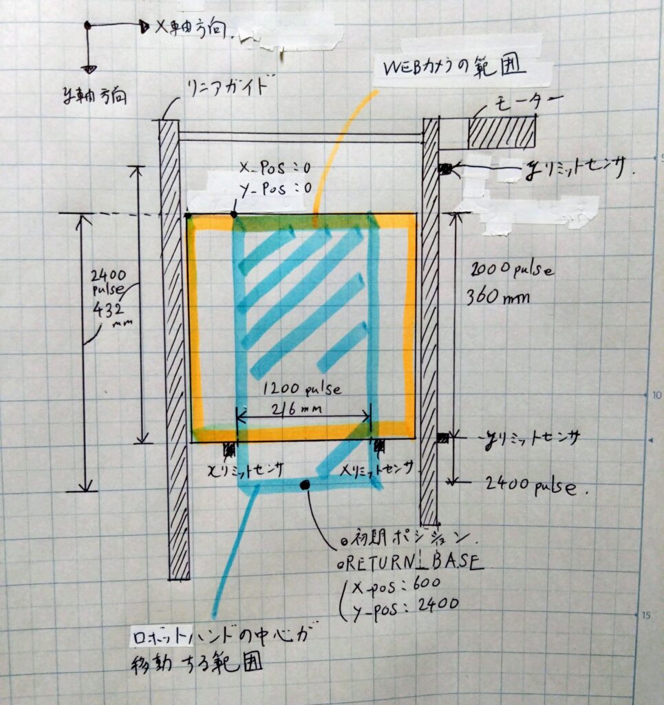
初期ポジションには手動で動かしておくものとする。

Arduino側に送信するコマンド例
ロボットハンドの移動位置はJetsonNano側からArduinoに送信されるパルス数によって決まる。
例えば以下のコマンドを送信すると、左方向に400pulse(72mm)、前方向に400pulse(72mm)、上方向に400pulse(72mm)移動する。
・START L 0400 F 0400 U 0400 O
同様にほかのコマンド例を示す。コマンドのフォーマットは以下のように設定している。
START␣左右方向(LまたはR)␣移動パルス␣前後方向(FまたはB)␣移動パルス␣上下方向(UまたはD)␣移動パルス␣開閉方向(OまたはC)
START L 0200 F 0000 D 0000 O 左方向
START R 0200 F 0000 D 0000 O 右方向
START R 0000 F 0200 D 0000 O 前方向
START R 0000 F 0200 D 0000 O 後方向
START L 0000 F 0000 U 0200 O 上昇
START L 0000 F 0000 D 0200 O 下降
START R 0000 F 0000 D 0000 O 開く
START R 0000 F 0000 D 0000 C 閉じる
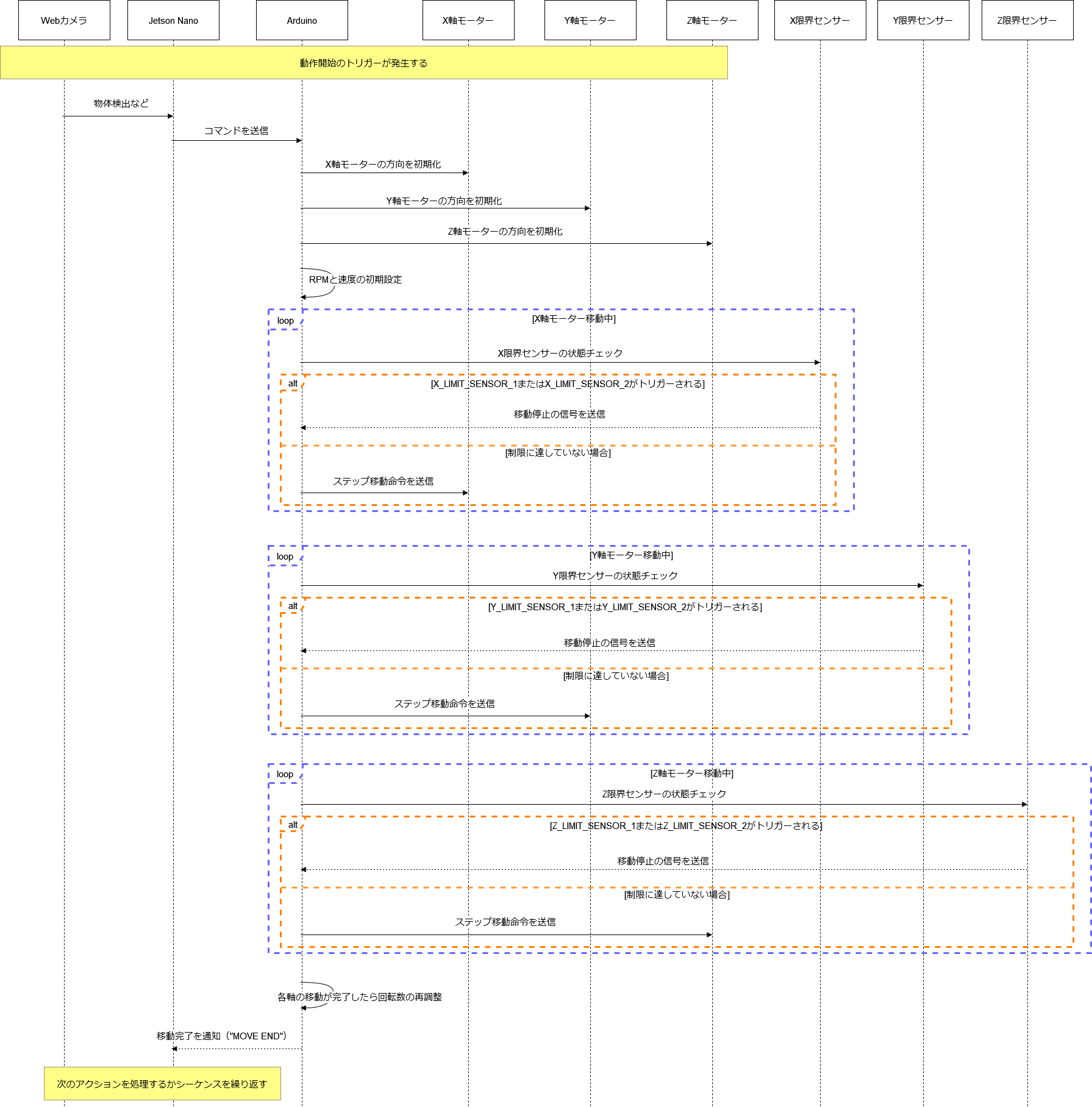
Arduino側のシーケンス図
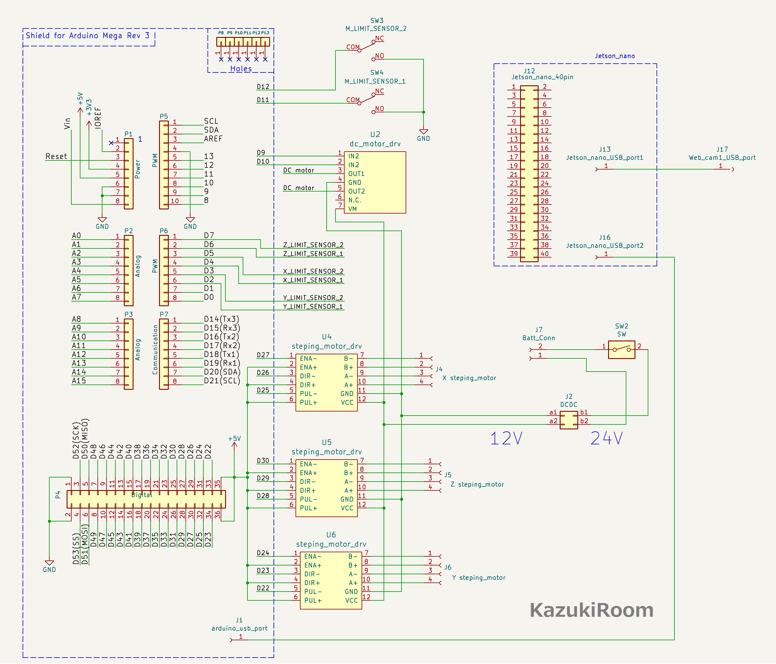
リニアガイド・Arduino・JetosonNanoの回路図
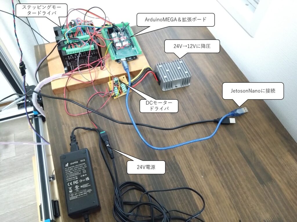
回路は以下のように接続する。今回は12VのDCモーターも利用しているため、駆動用の電源は24Vから12Vに降圧している。
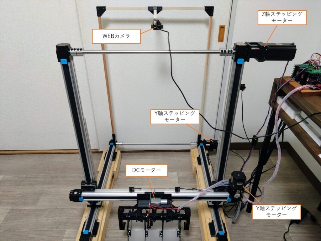
リニアガイドの組み立て
スイッチの1、2、3はパルス数(MOTOR_STEPS)に合わせて切り替える。今回は400のため、ON・OFF・ONに設定する。
スイッチの4、5、6はリニアガイドにかかる負荷に合わせて切り替える。Z軸は一番負荷がかかる予定なので4、5、6のスイッチを全てOFFにしてトルクを最大にする。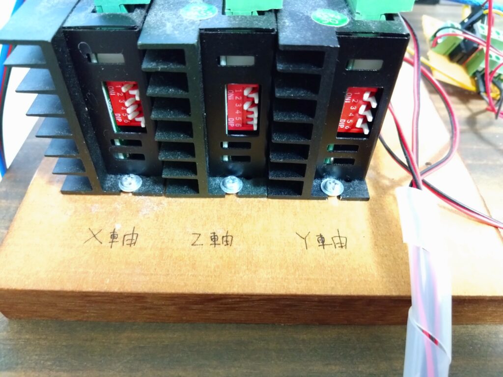
Arduino側の処理
まずはArduinoに書き込むソースは以下のようにする。シリアル通信で文字列を取得し、文字列に含まれるパラメータを判定してステッピングモータードライバを制御する。
|
1 2 3 4 5 6 7 8 9 10 11 12 13 14 15 16 17 18 19 20 21 22 23 24 25 26 27 28 29 30 31 32 33 34 35 36 37 38 39 40 41 42 43 44 45 46 47 48 49 50 51 52 53 54 55 56 57 58 59 60 61 62 63 64 65 66 67 68 69 70 71 72 73 74 75 76 77 78 79 80 81 82 83 84 85 86 87 88 89 90 91 92 93 94 95 96 97 98 99 100 101 102 103 104 105 106 107 108 109 110 111 112 113 114 115 116 117 118 119 120 121 122 123 124 125 126 127 128 129 130 131 132 133 134 135 136 137 138 139 140 141 142 143 144 145 146 147 148 149 150 151 152 153 154 155 156 157 158 159 160 161 162 163 164 165 166 167 168 169 170 171 172 173 174 175 176 177 178 179 180 181 182 183 184 185 186 187 188 189 190 191 192 193 194 195 196 197 198 199 200 201 202 203 204 205 206 207 208 209 210 211 212 213 214 215 216 217 218 219 220 221 222 223 224 225 226 227 228 229 230 231 232 233 234 235 236 237 238 239 240 241 242 243 244 245 246 247 248 249 250 251 252 253 254 255 256 257 258 259 260 261 262 263 264 265 266 267 268 269 270 271 272 273 274 275 276 277 278 279 280 281 282 283 284 285 286 287 288 289 290 291 292 293 294 295 296 297 298 299 300 301 302 303 304 305 306 307 308 309 310 311 312 313 314 315 316 317 318 319 320 321 322 323 324 325 326 327 328 329 330 331 332 333 334 335 336 337 338 339 340 341 342 343 344 345 346 347 348 349 350 351 352 353 354 355 356 357 358 359 360 361 362 363 364 365 366 367 368 369 370 371 372 373 374 375 376 377 378 379 380 381 382 383 384 385 386 387 388 389 390 391 392 393 394 395 396 397 398 399 400 401 402 403 404 405 406 407 408 409 410 411 412 413 414 415 416 417 418 419 420 421 422 423 424 425 |
const int MOTOR_STEPS = 400; // 1回転あたりのステップ数 [step/rev] // 各軸のピン設定 const int X_PUL = 25; // X軸のパルス信号ピン const int X_DIR = 26; // X軸の方向制御ピン const int X_ENA = 27; // X軸の有効制御ピン const int X_LIMIT_SENSOR_1 = 4; // X軸のリミットセンサー1 const int X_LIMIT_SENSOR_2 = 5; // X軸のリミットセンサー2 const int Y_PUL = 22; // Y軸のパルス信号ピン const int Y_DIR = 23; // Y軸の方向制御ピン const int Y_ENA = 24; // Y軸の有効制御ピン const int Y_LIMIT_SENSOR_1 = 2; // Y軸のリミットセンサー1 const int Y_LIMIT_SENSOR_2 = 3; // Y軸のリミットセンサー2 const int Z_PUL = 28; // Z軸のパルス信号ピン const int Z_DIR = 29; // Z軸の方向制御ピン const int Z_ENA = 30; // Z軸の有効制御ピン const int Z_LIMIT_SENSOR_1 = 6; // Z軸のリミットセンサー1 const int Z_LIMIT_SENSOR_2 = 7; // Z軸のリミットセンサー2 // ロボットハンドのピン設定 const int IN1 = 9; // ハンドの制御ピン1 const int IN2 = 10; // ハンドの制御ピン2 const int M_LIMIT_SENSOR_1 = 11; // ハンド用のリミットセンサー1 const int M_LIMIT_SENSOR_2 = 12; // ハンド用のリミットセンサー2 // 各軸の移動フラグ bool X_MOVE_FLG = false; // X軸の移動フラグ bool Y_MOVE_FLG = false; // Y軸の移動フラグ bool Z_MOVE_FLG = false; // Z軸の移動フラグ String X_DIR_IN = "LOW"; // X軸の方向入力 String Y_DIR_IN = "LOW"; // Y軸の方向入力 String Z_DIR_IN = "LOW"; // Z軸の方向入力 int X_STEPS_IN = 0; // X軸の指定ステップ数 int Y_STEPS_IN = 0; // Y軸の指定ステップ数 int Z_STEPS_IN = 0; // Z軸の指定ステップ数 int xPulseWidth = 400; // X軸のパルス幅 [us] int yPulseWidth = 400; // Y軸のパルス幅 [us] int zPulseWidth = 400; // Z軸のパルス幅 [us] int SetRpm_Max = 150; // 最大目標回転数 [rpm] String SUB_7_IN = "O"; // ロボットハンドの入力文字列 int xPulState = LOW; // X軸のPULピンの状態 int yPulState = LOW; // Y軸のPULピンの状態 int zPulState = LOW; // Z軸のPULピンの状態 long xPreviousMillis = 0; // X軸の前回の時間記録 long yPreviousMillis = 0; // Y軸の前回の時間記録 long zPreviousMillis = 0; // Z軸の前回の時間記録 int x = 0; // X軸の移動量 int y = 0; // Y軸の移動量 int z = 0; // Z軸の移動量 int calculatePulseWidth(int rpm) { /* 引数: rpm: 目標回転数 [rpm] 処理内容: 引数の目標RPMからステッピングモーターのパルス幅 (パルス周期の半分)をマイクロ秒単位で算出して返却します。 */ if (rpm <= 0) { return 0; // エラー処理 } float stepsPerSecond = (float)rpm / 60 * MOTOR_STEPS; // ステップ/秒 unsigned long microsecondsPerStep = 1000000 / stepsPerSecond; // マイクロ秒/ステップ int pulseWidth = microsecondsPerStep / 2; // パルス幅 [us] return pulseWidth; } int calculatePulseWidth(int rpm, int current_step, int totalSteps) { /* 引数: rpm: 目標回転数 [rpm] current_step: 現在のステップ数 totalSteps: 最終的なステップ数 処理内容: 引数の目標RPMからステッピングモーターのパルス幅 (パルス周期の半分)をマイクロ秒単位で算出して返却します。 台形制御で序盤は加速、中盤は定速、終盤は減速するように制御します。 */ if (rpm <= 0) { return 0; // エラー処理 } float stepsPerSecond = (float)rpm / 60 * MOTOR_STEPS; // ステップ/秒 unsigned long microsecondsPerStep = 1000000 / stepsPerSecond; // マイクロ秒/ステップ int pulseWidth = microsecondsPerStep / 2; // パルス幅 [us] // 加速および減速に利用する初期パルス幅と最小パルス幅を定義 const int initialPulseWidth = 1500; // 初期パルス幅 [us] const int minPulseWidth = pulseWidth; // 最小パルス幅 // 加速と減速に使用するステップ数を定義 int accelerationSteps = 20; // 加速に使用するステップ数 int decelerationSteps = 50; // 減速に使用するステップ数 int changeOverPoint = totalSteps - decelerationSteps; // 加速フェーズではパルス幅を徐々に狭めていきます。 if (current_step < accelerationSteps) { int stepAdjustment = current_step * ((initialPulseWidth - minPulseWidth) / accelerationSteps); pulseWidth = initialPulseWidth - stepAdjustment; if (pulseWidth < minPulseWidth) { pulseWidth = minPulseWidth; } } // 減速フェーズではパルス幅を徐々に広げていきます。 else if (current_step >= changeOverPoint) { int stepAdjustment = (current_step - changeOverPoint) * ((initialPulseWidth - minPulseWidth) / decelerationSteps); pulseWidth = minPulseWidth + stepAdjustment; if (pulseWidth > initialPulseWidth) { pulseWidth = initialPulseWidth; } } // 定速フェーズにおいては、加速/減速のどちらでもありませんので、最小パルス幅をそのまま使います。 return pulseWidth; } void MOVE() { /* 引数: なし 処理内容: whileループ内で各軸(X、Y、Z)の移動を制御します。 それぞれの軸ごとに、目標ステップ数(X_STEPS_IN、Y_STEPS_IN、Z_STEPS_IN)と回転方向(X_DIR_IN、Y_DIR_IN、Z_DIR_IN)を参照し、制御を行います。 移動が完了したら、各PULピンをLOWに設定し、ループから抜けます。 */ while (true) { // 無限ループで移動処理を実行 // X軸の移動制御 if (x < X_STEPS_IN) { // X軸の移動が必要な場合 X_MOVE_FLG = (X_DIR_IN == "LOW") ? (digitalRead(X_LIMIT_SENSOR_2) == 0 ? false : true) : (digitalRead(X_LIMIT_SENSOR_1) == 0 ? false : true); } else { // 指定ステップ数を超えた場合は移動しない X_MOVE_FLG = false; } // Y軸の移動制御 if (y < Y_STEPS_IN) { // Y軸の移動が必要な場合 Y_MOVE_FLG = (Y_DIR_IN == "LOW") ? (digitalRead(Y_LIMIT_SENSOR_2) == 0 ? false : true) : (digitalRead(Y_LIMIT_SENSOR_1) == 0 ? false : true); } else { // 指定ステップ数を超えた場合は移動しない Y_MOVE_FLG = false; } // Z軸の移動制御 if (z < Z_STEPS_IN) { // Z軸の移動が必要な場合 Z_MOVE_FLG = (Z_DIR_IN == "LOW") ? (digitalRead(Z_LIMIT_SENSOR_2) == 0 ? false : true) : (digitalRead(Z_LIMIT_SENSOR_1) == 0 ? false : true); } else { // 指定ステップ数を超えた場合は移動しない Z_MOVE_FLG = false; } //////////////////////////////////////////////////////////////// // ロボットハンドの信号を送信 if (SUB_7_IN == "O" || SUB_7_IN == "C") { // "O" または "C" の場合のみ処理を実行 if (SUB_7_IN == "O") { // 開く指示の場合 if (digitalRead(M_LIMIT_SENSOR_1) == LOW) { // センサー1がトリガーされた場合 digitalWrite(IN1, LOW); // ハンドを停止 digitalWrite(IN2, LOW); // ハンドを停止 SUB_7_IN = "END"; // 完了ステータスに変更 } else { digitalWrite(IN1, LOW); // 一方を低電位に digitalWrite(IN2, HIGH); // 他方を高電位に } } else { // 閉じる指示の場合 if (digitalRead(M_LIMIT_SENSOR_2) == LOW) { // センサー2がトリガーされた場合 digitalWrite(IN1, LOW); // ハンドを停止 digitalWrite(IN2, LOW); // ハンドを停止 SUB_7_IN = "END"; // 完了ステータスに変更 } else { digitalWrite(IN1, HIGH); // 一方を高電位に digitalWrite(IN2, LOW); // 他方を低電位に } } } else { // "O" または "C" 以外の場合 // ストップ状態にする digitalWrite(IN1, LOW); digitalWrite(IN2, LOW); SUB_7_IN = "END"; } //////////////////////////////////////////////////////////////// // 全ての移動フラグがfalseで、ロボットハンドが終了状態の場合 if (!X_MOVE_FLG && !Y_MOVE_FLG && !Z_MOVE_FLG && SUB_7_IN == "END") { Serial.println("break"); // ブレーク条件成立時にメッセージ出力 break; // ループを抜ける } //////////////////////////////////////////////////////////////// // 台形制御でパルス幅を算出 xPulseWidth = calculatePulseWidth(SetRpm_Max, x, X_STEPS_IN); yPulseWidth = calculatePulseWidth(SetRpm_Max, y, Y_STEPS_IN); zPulseWidth = calculatePulseWidth(SetRpm_Max, z, Z_STEPS_IN); outPUL(); // ステッピングモーターを動作させる } // 各軸の移動量をリセット x = 0; // X軸移動量をリセット y = 0; // Y軸移動量をリセット z = 0; // Z軸移動量をリセット } int setDIR() { /* 引数: なし 処理内容: X_DIR_IN、Y_DIR_IN、Z_DIR_INの値を参照し、ステッピングモーターの回転方向を設定します。 */ // 各軸の方向を配列でまとめて管理 const int dirPins[] = {X_DIR, Y_DIR, Z_DIR}; const String dirInputs[] = {X_DIR_IN, Y_DIR_IN, Z_DIR_IN}; for (int i = 0; i < 3; i++) { if (dirInputs[i] == "HIGH") { digitalWrite(dirPins[i], HIGH); // 回転方向を設定 } else if (dirInputs[i] == "LOW") { digitalWrite(dirPins[i], LOW); // 回転方向を設定 } } } int outPUL() { /* 引数: なし 処理内容: それぞれのフラグがtrueの場合、対応するPULピン(X_PUL、Y_PUL、Z_PUL)をHIGH・LOWに設定してパルス信号を生成します。 */ unsigned long currentMicros = micros(); if (currentMicros - xPreviousMillis > xPulseWidth) { xPreviousMillis = currentMicros; if (X_MOVE_FLG == true) { if (xPulState == LOW) { xPulState = HIGH; x++; } else { xPulState = LOW; } digitalWrite(X_PUL, xPulState); } } if (currentMicros - yPreviousMillis > yPulseWidth) { yPreviousMillis = currentMicros; if (Y_MOVE_FLG == true) { if (yPulState == LOW) { yPulState = HIGH; y++; } else { yPulState = LOW; } digitalWrite(Y_PUL, yPulState); } } if (currentMicros - zPreviousMillis > zPulseWidth) { zPreviousMillis = currentMicros; if (Z_MOVE_FLG == true) { if (zPulState == LOW) { zPulState = HIGH; z++; } else { zPulState = LOW; } digitalWrite(Z_PUL, zPulState); } } } void setup() { /* 引数: なし 処理内容: セットアップ処理を行います。シリアル通信を開始し、各ピンのモードを設定します。 */ Serial.begin(9600); // シリアル通信の初期化 // 各ピンの設定 pinMode(X_PUL, OUTPUT); // X軸パルスピンを出力に設定 pinMode(X_DIR, OUTPUT); // X軸方向ピンを出力に設定 pinMode(X_ENA, OUTPUT); // X軸有効ピンを出力に設定 pinMode(Y_PUL, OUTPUT); // Y軸パルスピンを出力に設定 pinMode(Y_DIR, OUTPUT); // Y軸方向ピンを出力に設定 pinMode(Y_ENA, OUTPUT); // Y軸有効ピンを出力に設定 pinMode(Z_PUL, OUTPUT); // Z軸パルスピンを出力に設定 pinMode(Z_DIR, OUTPUT); // Z軸方向ピンを出力に設定 pinMode(Z_ENA, OUTPUT); // Z軸有効ピンを出力に設定 pinMode(IN1, OUTPUT); // ハンド制御ピン1を出力に設定 pinMode(IN2, OUTPUT); // ハンド制御ピン2を出力に設定 // 各センサーの設定 pinMode(X_LIMIT_SENSOR_1, INPUT); // X軸リミットセンサー1を入力に設定 pinMode(X_LIMIT_SENSOR_2, INPUT); // X軸リミットセンサー2を入力に設定 pinMode(Y_LIMIT_SENSOR_1, INPUT); // Y軸リミットセンサー1を入力に設定 pinMode(Y_LIMIT_SENSOR_2, INPUT); // Y軸リミットセンサー2を入力に設定 pinMode(Z_LIMIT_SENSOR_1, INPUT); // Z軸リミットセンサー1を入力に設定 pinMode(Z_LIMIT_SENSOR_2, INPUT); // Z軸リミットセンサー2を入力に設定 pinMode(M_LIMIT_SENSOR_1, INPUT_PULLUP); // ハンド用リミットセンサー1を入力に設定 pinMode(M_LIMIT_SENSOR_2, INPUT_PULLUP); // ハンド用リミットセンサー2を入力に設定 Serial.println("START"); } void loop() { /* 引数: なし 処理内容: メインループ処理を行います。シリアルポートからのデータ受信を監視し、 コマンドを処理して移動指示を実行します。 */ if (Serial.available() > 0) { // シリアルポートにデータがある場合 String cmd = Serial.readStringUntil('\n'); // 改行までの文字列を読み取る processCommand(cmd); // 受け取ったコマンドを処理する関数を呼び出す executeMovement(); // 実際の移動を実行する関数を呼び出す } } void processCommand(String cmd) { /* 引数: cmd - 処理するコマンド文字列 処理内容: 受信したコマンドを解析し、各軸の方向やステップ数を設定します。 */ if (!cmd.startsWith("START")) return; // コマンドが"START"で始まらない場合は終了 // コマンドの解析 String directionX = cmd.substring(6, 7); // X軸の方向(LまたはR)を取得 X_STEPS_IN = cmd.substring(8, 12).toInt(); // X軸の目標ステップ数を整数型に変換 String directionY = cmd.substring(13, 14); // Y軸の方向(FまたはB)を取得 Y_STEPS_IN = cmd.substring(15, 19).toInt(); // Y軸の目標ステップ数を整数型に変換 String directionZ = cmd.substring(20, 21); // Z軸の方向(UまたはD)を取得 Z_STEPS_IN = cmd.substring(22, 26).toInt(); // Z軸の目標ステップ数を整数型に変換 SUB_7_IN = cmd.substring(27, 28); // ロボットアームの開閉指示(CまたはO)を取得 // ディレクション設定 setDirection(directionX, directionY, directionZ); // 各軸の方向を設定 } void setDirection(String dx, String dy, String dz) { /* 引数: dx - X軸の方向(LまたはR) dy - Y軸の方向(FまたはB) dz - Z軸の方向(UまたはD) 処理内容: 各軸の回転方向を設定するため、グローバル変数に値を代入します。 */ // X軸の回転方向を設定 X_DIR_IN = (dx == "L") ? "LOW" : "HIGH"; // LならLOW、RならHIGH // Y軸の回転方向を設定 Y_DIR_IN = (dy == "F") ? "LOW" : "HIGH"; // FならLOW、BならHIGH // Z軸の回転方向を設定 Z_DIR_IN = (dz == "U") ? "LOW" : "HIGH"; // UならLOW、DならHIGH } void executeMovement() { /* 引数: なし 処理内容: 各軸を有効にし、設定された方向とステップ数に基づいて移動を実行します。 */ // 各軸を有効にする digitalWrite(X_ENA, HIGH); // X軸を有効化 digitalWrite(Y_ENA, HIGH); // Y軸を有効化 digitalWrite(Z_ENA, HIGH); // Z軸を有効化 setDIR(); // 各軸の方向を設定する関数を呼び出す MOVE(); // 実際の移動を実行する関数を呼び出す Serial.println("Arduino MOVE END"); // 移動完了メッセージを表示 // 各軸を無効にする digitalWrite(X_ENA, LOW); // X軸を無効化 digitalWrite(Y_ENA, LOW); // Y軸を無効化 } |
JetsonNano側の処理
JetsonNano側の処理については省略する。Webカメラから映像を取り込み、物体検出を行ったのち、Arduinoへ文字列を送信している。
実際に動かしてみた
まずは以下の準備を行う。
①ArduinoとJetosonNanoをUSBケーブルで接続
②JetosonNanoとモニターをHDMIケーブルで接続
③JetosonNanoにモバイルバッテリーを接続し、電源を入れる
④リニアガイドの位置を初期ポジションに移動しておく
⑤リニアガイドの動力電源を入れる
⑥JetosonNanoのターミナルを起動し、以下のコマンドを実行する
|
1 2 |
cd ~/workspace/catkin_ws/src/jetbot_ros/scripts python3 guide_camera.py |
上記を実行してしばらくするとリニアガイドの初期動作(UP動作)が開始される。
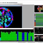
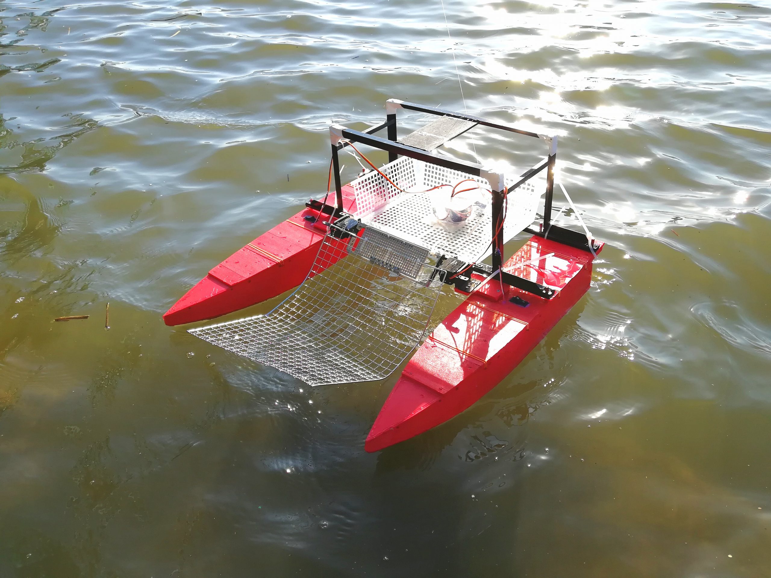
今日もペットボトルと空き缶の自動回収を試してみました。右上はリニアガイドの上部に取り付けたWebカメラの映像です。
なるべく色んな形状・大きさのものを回収できるようになればいいなと思っています。 pic.twitter.com/546036yRmm— Kazuki (@RoomKazuki) March 28, 2023
台形制御を導入
Arduinoのプログラムを最適化し、騒音対策で台形制御を導入してみた。また、リニアガイドの固定金具の下に防振ゴムを置き、防振対策を行ってみた。結果として、騒音のほうはまだかなりする状態となっている。
台形制御を導入したりArduinoの処理を最適化したりしました。防振ゴムで騒音対策もやってみましたがまだまだうるさいですね。。 pic.twitter.com/LZIamNCb0K
— Kazuki (@RoomKazuki) October 5, 2024